Relay: Difference between revisions
HuntaBadday (talk | contribs) Created page with "{{Infobox component | title=Relay | caption=Relay | id=MHG.Relay | io.propagationDelay=1 | io.maxInputs=3 | io.minInputs=3 | io.outputs=2 }} The relay is a component which can pass a signal between the two side pins bi-directionally while the top pin (Enable) is HIGH. == Timing == The Relay has a latency of 0 ticks for a signal to pass between the side pins, but has a switching latency of 1 tick. So in the instance the enable pin is HIGH, it will take 1 tick to switch t..." |
|||
| (5 intermediate revisions by 3 users not shown) | |||
| Line 6: | Line 6: | ||
| io.maxInputs=3 | | io.maxInputs=3 | ||
| io.minInputs=3 | | io.minInputs=3 | ||
| io.outputs= | | io.outputs=0 | ||
}} | }} | ||
The '''Relay''' is a [[component]] used for [[digital logic]]. The input on the top is used to control whether signals can pass through the inputs on the sides, making it useful for controlling where signals can propagate to. | |||
The Relay | |||
== | == Behavior == | ||
When the input on the top of a Relay is {{on}}, signals can pass freely between the two side inputs with no delay, as if they were [[Peg|Pegs]] connected by a [[wire]]. However, when the input on the top is {{off}}, the side inputs do not affect each other. | |||
The Relay takes one [[tick]] to change state between "open" and "closed" when the input on the top changes state. While the Relay is open, signals pass through the side inputs instantly (in 0 ticks). | |||
=== Differences from an AND Gate === | |||
{{todo|this section}} | |||
== Placement == | |||
XOR Gates have two attachment points, one for each square covered by the body of the component. These attachment points can be placed in the center of a [[Circuit Board]] square or on top of a [[Mount]]. | |||
{{Navbox components}} | |||
[[Category:Vanilla components]] | |||
[[Category:Circuitry components]] | |||
Latest revision as of 23:32, 8 September 2025
 Relay | |
| Component info | |
|---|---|
| Internal ID |
MHG.Relay |
| Configurable | No |
| Input and output | |
| Input count | 3 |
| Output count | 0 |
| Propagation delay | 1 tick |
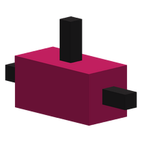
The Relay is a component used for digital logic. The input on the top is used to control whether signals can pass through the inputs on the sides, making it useful for controlling where signals can propagate to.
Behavior
When the input on the top of a Relay is ON, signals can pass freely between the two side inputs with no delay, as if they were Pegs connected by a wire. However, when the input on the top is OFF, the side inputs do not affect each other.
The Relay takes one tick to change state between "open" and "closed" when the input on the top changes state. While the Relay is open, signals pass through the side inputs instantly (in 0 ticks).
Differences from an AND Gate
Placement
XOR Gates have two attachment points, one for each square covered by the body of the component. These attachment points can be placed in the center of a Circuit Board square or on top of a Mount.

