
Decoder: Difference between revisions
First iteration of the decoder page |
|||
| (5 intermediate revisions by 2 users not shown) | |||
| Line 1: | Line 1: | ||
; '''Decoder''' | ; '''Decoder''' | ||
: In ''Logic World'', a '''Decoder''' is a circuit that takes a binary input and activates one specific output bit | : In ''Logic World'', a '''Decoder''' is a circuit that takes a binary input and activates one specific output bit corresponding to that input. | ||
: It is commonly used to select one | : It is commonly used to select one element out of many, for example a cell in memory. | ||
: | : The Decoder always outputs a single bit. | ||
: Effectively it's translating a binary value into a [[wikipedia:Unary_numeral_system|unary]] value. | |||
: [[File:4bit-decoder.png|alt=4-bit decoder. Input on the left is 1110. The 14th output bit on the right is activated.|thumb|4-bit decoder. Input on the left is 1110. The 14th output bit on the right is activated.]] | |||
[[File: | == Construction == | ||
A Decoder is one of the simplest circuits to build. | |||
First, determine how many bits you need. | |||
The number of output bits from input bits is given by: | |||
:<math>o = 2^i</math> | |||
And vice versa: | |||
:<math>i = \log_2(o)</math> | |||
So, if you want 256 outputs, you will need a decoder with 8 input bits. | |||
Each output has a specific pattern of {{on}} and {{off}} bits coming from the input. The circuit is basically a number of [[AND Gate|AND]] gates for each possible combination. | |||
Here are the steps to build it: | |||
* Place a row of input items. | |||
* Connect each input bit to both a [[Inverter|NOT]] gate and a [[Buffer]].The NOT gate is required to have the inverted value and the Buffer is required to match the delay with the NOT gate. | |||
* Place a row of NOT gates to serve as the outputs. | |||
* Go through each output NOT gate and connect them to the corresponding inputs (normal or inverted) to match its binary value. For example, the output corresponding to number 12 (binary 1100) should receive the following binary values: | |||
** 1st bit – normal | |||
** 2nd bit – normal | |||
** 3rd bit – inverted | |||
** 4th bit – inverted | |||
:and so on for each value. | |||
You can design a decoder in different ways. If you are building one for the first time, you may want to explicitly place each wire and gate to match the real electronic analog or to be visually understandable. | |||
When you become more experienced, you can skip unnecessary details and make it as simple as the screenshot above demonstrates. This design, optimized for speed and size, uses the trick of connecting wires from '''output''' pins directly to the required items, avoiding additional buffers and wire routing. On the screenshot below you can see the side view and how it allows it to make it compact. | |||
[[File:Decoder-side.png|thumb|center|alt=Side view of the decoder|Side view of the decoder]] | |||
== Speed == | |||
The compact design above computes the output in 2 ticks. | |||
== Part of == | |||
Decoders are used primarily as part of the following circuits: | |||
[[RAM]], [[ROM]]<br> | |||
[[CU|Control Unit]]<br> | |||
[[Multiplexer]], [[Demultiplexer]]<br> | |||
[[Lookup_Table]]<br> | |||
== See also == | |||
* [[Encoder]] | |||
* [[Lookup Table]] | |||
Latest revision as of 22:55, 12 September 2025
- Decoder
- In Logic World, a Decoder is a circuit that takes a binary input and activates one specific output bit corresponding to that input.
- It is commonly used to select one element out of many, for example a cell in memory.
- The Decoder always outputs a single bit.
- Effectively it's translating a binary value into a unary value.
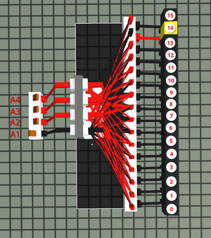
4-bit decoder. Input on the left is 1110. The 14th output bit on the right is activated.

Construction
A Decoder is one of the simplest circuits to build. First, determine how many bits you need. The number of output bits from input bits is given by:
And vice versa:
So, if you want 256 outputs, you will need a decoder with 8 input bits. Each output has a specific pattern of ON and OFF bits coming from the input. The circuit is basically a number of AND gates for each possible combination.
Here are the steps to build it:
- Place a row of input items.
- Connect each input bit to both a NOT gate and a Buffer.The NOT gate is required to have the inverted value and the Buffer is required to match the delay with the NOT gate.
- Place a row of NOT gates to serve as the outputs.
- Go through each output NOT gate and connect them to the corresponding inputs (normal or inverted) to match its binary value. For example, the output corresponding to number 12 (binary 1100) should receive the following binary values:
- 1st bit – normal
- 2nd bit – normal
- 3rd bit – inverted
- 4th bit – inverted
- and so on for each value.
You can design a decoder in different ways. If you are building one for the first time, you may want to explicitly place each wire and gate to match the real electronic analog or to be visually understandable.
When you become more experienced, you can skip unnecessary details and make it as simple as the screenshot above demonstrates. This design, optimized for speed and size, uses the trick of connecting wires from output pins directly to the required items, avoiding additional buffers and wire routing. On the screenshot below you can see the side view and how it allows it to make it compact.

Speed
The compact design above computes the output in 2 ticks.
Part of
Decoders are used primarily as part of the following circuits:
RAM, ROM
Control Unit
Multiplexer, Demultiplexer
Lookup_Table