Lookup Table: Difference between revisions
Made it much simpler by removing some wording. Added a LUT definition using a template. Made formulas clearer. |
Big addition - using LUT to store characters |
||
| (3 intermediate revisions by one other user not shown) | |||
| Line 1: | Line 1: | ||
{{LUT}} | |||
The term "Lookup tables" is often used interchangeably with [[ROM]] and [[Cache]], but they are not always the same. | |||
This article will focus on two usages: | |||
*Formulas | |||
*Storing characters for a screen | |||
== Formulas == | |||
Using LUTs to implement certain formulas/functions is useful, because any arbitrary logic formula can always be represented in [https://en.wikipedia.org/wiki/Disjunctive_normal_form disjunctive normal form]. | |||
In simple terms, the output of the formula is computed using a single OR operation on inputs coming from a number of AND gates. Each AND gate represents a distinct case where the output is supposed to be ''true''. | |||
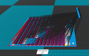
[[File:5BitEqualityLut.png|alt=5 bit equality LUT|thumb|5 bit equality LUT]] | [[File:5BitEqualityLut.png|alt=5 bit equality LUT|thumb|5 bit equality LUT]] | ||
=== Construction === | |||
== Construction == | A LUT for formulas is implemented by first creating a list of all input combinations that should lead to a ''true'' output. From this list, the LUT can then be built quite easily. | ||
A LUT is implemented by first creating a list of all input combinations that should lead to a ''true'' output. From this list, the LUT can then be built quite easily. | It consists of multiple relay chains that are simply OR-ed together at the end, where one chain corresponds to one input assignment that should lead to a truthy output value. The aforementioned relay chains are started by a single NOT-gate whose inputs are all signals that are ''false'' in the case where a ''true'' output is expected, followed by a set of relays where the top input is expected to be ''true'' for such a result. | ||
It consists of multiple relay chains that are simply OR-ed together at the end, where one chain corresponds to one input | |||
We can avoid delays by not using [[Buffer|Buffers]], which makes the circuit perform the operation in a single tick. | |||
In that case, back-propagation must be prevented by using [[Fast Buffer|Fast Buffers]]. | |||
Each chain therefore needs one component per input (Relays plus Fast Buffers), along with one NOT-gate if there are any inputs that are supposed to be ''off''. | |||
==== Pros and Cons ==== | |||
Relative to other circuits performing a specific function. | |||
Pros: | |||
*Fastest speed with constant delay, ideally 1 tick. | |||
Cons: | |||
*Hardcoded, very difficult to change/add/remove combinations. | |||
=== Complexity to build === | ==== Complexity to build ==== | ||
When building a LUT as described above, we can count the total number of components as: | When building a LUT as described above, we can count the total number of components as: | ||
:<math>C = c \cdot (1 + n)</math> | :<math>C = c \cdot (1 + n)</math> | ||
Where: | Where: | ||
<math>c</math> is the number of distinct '''chains''' (true outputs),<br> | <math>c</math> is the number of distinct '''chains''' (true outputs),<br> | ||
<math>n</math> is the number of inputs. | <math>n</math> is the number of inputs. | ||
Assuming half of all possible input combinations lead to a true output: | |||
:<math>c = 50\% \cdot (2^n) = 2^{n-1}</math> | |||
So in total: | So in total: | ||
:<math>C = 2^{n-1} \cdot (1 + n)</math> | :<math>C = 2^{n-1} \cdot (1 + n)</math> | ||
In theory | |||
In theory this approaches: | |||
:<math>\mathcal{O}(2^n)</math> | |||
In other words, the required component count grows exponentially with the number of inputs, assuming the number of true-output cases also scales exponentially. | In other words, the required component count grows exponentially with the number of inputs, assuming the number of true-output cases also scales exponentially. | ||
While LUT circuits become very expensive in terms of components, they are | == Storing characters for a screen == | ||
You may also be familiar with LUTs from programming, where they are used for hardcoded arrays to store permanent data. | |||
In ''Logic World'' such LUTs (also called ROM) store hardcoded binary values that are easily accessible for any purpose. The following example shows how to store characters for a screen. Although you can use it to store other data, such as constants, unchanging programs, or music notes. | |||
=== Construction === | |||
The simplest way to build it is to use a [[decoder]] as a base component. Steps to build: | |||
*Place the decoder towards the input side | |||
*Place output items, such as pegs, sockets, etc. | |||
*Go through each output bit in the decoder one by one and connect wires to the output items in the needed pattern | |||
The screenshot below demonstrates wiring to store two different characters on the screen. The full LUT will have all the cases present at once. | |||
[[File:CharactersLUT.png|frame|center]] | |||
The example in the screenshot is very simple and direct, useful for ready-to-use segmented displays. For other purposes you may want to output LUT data onto a bus, instead of directly to the lamps. | |||
==== Pros and Cons ==== | |||
Relative to other types of memory. | |||
Pros: | |||
*Fastest speed with constant delay, usually 2 ticks. | |||
*Not very hard to build. | |||
Cons: | |||
*Still hardcoded, cannot be changed programmatically, only manually. | |||
==== Complexity to build ==== | |||
If using a decoder as a base component it will require the following parts: | |||
*1 [[decoder]] | |||
*Wires equal to the total number of {{on}} bits in all cases combined | |||
Complexity to build a decoder with '''n''' input bits is equal to: | |||
<math>\mathcal{O}(2^n)</math> | |||
== Conclusion == | |||
While LUT circuits become very expensive in terms of components, they are '''extremely fast'''. This makes them essential for designs that must run within strict time limits. For non-trivial functions, this speed is usually only achievable by using a LUT. | |||
{{todo|add infobox | {{todo|add infobox maybe?}} | ||
Latest revision as of 17:52, 10 September 2025
- Lookup table
- In Logic World, a Lookup table (LUT) is a circuit that explicitly encodes all possible input cases and assigns a specific output to each case.
- The output may be a single bit or a pattern of bits.
- Examples:
- read-only memory (ROM) (general example)
- storing characters for a screen (particular example)
- a hard-coded complex formula
The term "Lookup tables" is often used interchangeably with ROM and Cache, but they are not always the same.
This article will focus on two usages:
- Formulas
- Storing characters for a screen
Formulas
Using LUTs to implement certain formulas/functions is useful, because any arbitrary logic formula can always be represented in disjunctive normal form. In simple terms, the output of the formula is computed using a single OR operation on inputs coming from a number of AND gates. Each AND gate represents a distinct case where the output is supposed to be true.

Construction
A LUT for formulas is implemented by first creating a list of all input combinations that should lead to a true output. From this list, the LUT can then be built quite easily. It consists of multiple relay chains that are simply OR-ed together at the end, where one chain corresponds to one input assignment that should lead to a truthy output value. The aforementioned relay chains are started by a single NOT-gate whose inputs are all signals that are false in the case where a true output is expected, followed by a set of relays where the top input is expected to be true for such a result.
We can avoid delays by not using Buffers, which makes the circuit perform the operation in a single tick. In that case, back-propagation must be prevented by using Fast Buffers. Each chain therefore needs one component per input (Relays plus Fast Buffers), along with one NOT-gate if there are any inputs that are supposed to be off.
Pros and Cons
Relative to other circuits performing a specific function.
Pros:
- Fastest speed with constant delay, ideally 1 tick.
Cons:
- Hardcoded, very difficult to change/add/remove combinations.
Complexity to build
When building a LUT as described above, we can count the total number of components as:
Where:
is the number of distinct chains (true outputs),
is the number of inputs.
Assuming half of all possible input combinations lead to a true output:
So in total:
In theory this approaches:
In other words, the required component count grows exponentially with the number of inputs, assuming the number of true-output cases also scales exponentially.
Storing characters for a screen
You may also be familiar with LUTs from programming, where they are used for hardcoded arrays to store permanent data.
In Logic World such LUTs (also called ROM) store hardcoded binary values that are easily accessible for any purpose. The following example shows how to store characters for a screen. Although you can use it to store other data, such as constants, unchanging programs, or music notes.
Construction
The simplest way to build it is to use a decoder as a base component. Steps to build:
- Place the decoder towards the input side
- Place output items, such as pegs, sockets, etc.
- Go through each output bit in the decoder one by one and connect wires to the output items in the needed pattern
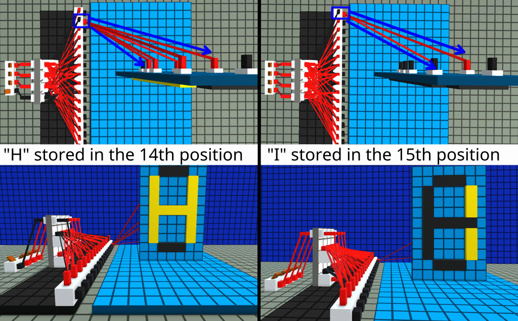
The screenshot below demonstrates wiring to store two different characters on the screen. The full LUT will have all the cases present at once.

The example in the screenshot is very simple and direct, useful for ready-to-use segmented displays. For other purposes you may want to output LUT data onto a bus, instead of directly to the lamps.
Pros and Cons
Relative to other types of memory.
Pros:
- Fastest speed with constant delay, usually 2 ticks.
- Not very hard to build.
Cons:
- Still hardcoded, cannot be changed programmatically, only manually.
Complexity to build
If using a decoder as a base component it will require the following parts:
- 1 decoder
- Wires equal to the total number of ON bits in all cases combined
Complexity to build a decoder with n input bits is equal to:
Conclusion
While LUT circuits become very expensive in terms of components, they are extremely fast. This makes them essential for designs that must run within strict time limits. For non-trivial functions, this speed is usually only achievable by using a LUT.

