Inverter Logic Gates: Difference between revisions
FoxFireFive (talk | contribs) m Undo revision 384 by FoxFireFive (talk) Tag: Undo |
FoxFireFive (talk | contribs) mNo edit summary Tags: Manual revert Visual edit |
||
| (7 intermediate revisions by the same user not shown) | |||
| Line 2: | Line 2: | ||
== Inverter AND Gate == | == Inverter AND Gate == | ||
[[File:Inverter AND.jpg|thumb|[[AND Gate]]]] | [[File:Inverter AND.jpg|thumb|[[AND Gate]]|200x200px]] | ||
An '''AND gate''' is a basic digital logic component whose output will be '''ON''' if '''all''' its inputs are '''ON'''. | An '''AND gate''' is a basic digital logic component whose output will be '''ON''' if '''all''' its inputs are '''ON'''. | ||
| Line 10: | Line 10: | ||
The Inverter AND gate has a latency of 2 ticks, so in the instance when all inputs are '''ON''', the output will become '''active''' 2 ticks later. | The Inverter AND gate has a latency of 2 ticks, so in the instance when all inputs are '''ON''', the output will become '''active''' 2 ticks later. | ||
| Line 20: | Line 15: | ||
== Inverter OR Gate == | == Inverter OR Gate == | ||
[[File:Inverter OR (Updated).jpg|thumb|[[OR Gate]]]] | [[File:Inverter OR (Updated).jpg|thumb|[[OR Gate]]|235x235px]] | ||
An '''OR Gate''' is a basic digital logic component whose output will be '''ON''' if '''any''' of its inputs are '''ON'''. | An '''OR Gate''' is a basic digital logic component whose output will be '''ON''' if '''any''' of its inputs are '''ON'''. | ||
| Line 28: | Line 23: | ||
The Inverter OR gate has a latency of 3 ticks, so in the instance when all inputs are '''ON''', the output will become '''active''' 3 ticks later. | The Inverter OR gate has a latency of 3 ticks, so in the instance when all inputs are '''ON''', the output will become '''active''' 3 ticks later. | ||
| Line 36: | Line 28: | ||
== Inverter XOR Gate == | == Inverter XOR Gate == | ||
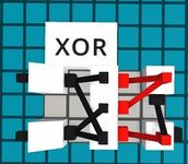
[[File:Inverter XOR.jpg|thumb|[[XOR Gate]]]] | [[File:Inverter XOR.jpg|thumb|[[XOR Gate]]|172x172px]] | ||
An '''XOR Gate''' is a basic digital logic component whose output will be '''ON''' if only '''one''' input is '''ON'''. | An '''XOR Gate''' is a basic digital logic component whose output will be '''ON''' if only '''one''' input is '''ON'''. | ||
| Line 42: | Line 34: | ||
The Inverter XOR gate has a latency of 3 ticks, so in the instance when all inputs are '''ON''', the output will become '''active''' 3 ticks later. | The Inverter XOR gate has a latency of 3 ticks, so in the instance when all inputs are '''ON''', the output will become '''active''' 3 ticks later. | ||
| Line 52: | Line 39: | ||
== Inverter NAND Gate == | == Inverter NAND Gate == | ||
[[File:Inverter NAND.jpg|thumb|[[NAND Gate]]]] | [[File:Inverter NAND.jpg|thumb|[[NAND Gate]]|200x200px]] | ||
A '''NAND gate''' is a basic digital logic component whose output will be '''OFF''' if '''all''' its inputs are '''ON'''. | A '''NAND gate''' is a basic digital logic component whose output will be '''OFF''' if '''all''' its inputs are '''ON'''. | ||
| Line 67: | Line 54: | ||
== Inverter NOR Gate == | == Inverter NOR Gate == | ||
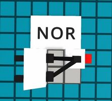
[[File:Inverter NOR.jpg|thumb|[[NOR Gate]]]] | [[File:Inverter NOR.jpg|thumb|[[NOR Gate]]|222x222px]] | ||
A '''NOR Gate''' is a basic digital logic component whose output will be '''OFF''' if '''any''' of its inputs are '''ON'''. | A '''NOR Gate''' is a basic digital logic component whose output will be '''OFF''' if '''any''' of its inputs are '''ON'''. | ||
| Line 75: | Line 62: | ||
The Inverter NOR gate has a latency of 2 ticks, so in the instance when all inputs are '''ON''', the output will become '''inactive''' 2 ticks later. | The Inverter NOR gate has a latency of 2 ticks, so in the instance when all inputs are '''ON''', the output will become '''inactive''' 2 ticks later. | ||
| Line 85: | Line 67: | ||
== Inverter XNOR Gate == | == Inverter XNOR Gate == | ||
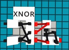
[[File:Inverter XNOR.jpg|thumb|[[XNOR Gate]]]] | [[File:Inverter XNOR.jpg|thumb|[[XNOR Gate]]|275x275px]] | ||
An '''XNOR Gate''' is a basic digital logic component whose output will be '''ON''' if all inputs are the same. | An '''XNOR Gate''' is a basic digital logic component whose output will be '''ON''' if all inputs are the same. | ||
Latest revision as of 21:23, 7 September 2025
Logic gates can be created using only the Inverter component and the Buffer component, with the exception of pegs for routing.
Inverter AND Gate

An AND gate is a basic digital logic component whose output will be ON if all its inputs are ON.
The Inverter AND gate's output will only be active if all of its inputs are ON. This is true no matter how many inputs the Inverter AND gate has.
To add more inputs, connect more inverters to the output inverter.
The Inverter AND gate has a latency of 2 ticks, so in the instance when all inputs are ON, the output will become active 2 ticks later.
Inverter OR Gate

An OR Gate is a basic digital logic component whose output will be ON if any of its inputs are ON.
The Inverter OR gate's output will be active if any of its inputs are ON. This is true no matter how many inputs the Inverter OR gate has.
To add more inputs, connect more buffers to the first inverter.
The Inverter OR gate has a latency of 3 ticks, so in the instance when all inputs are ON, the output will become active 3 ticks later.
Inverter XOR Gate

An XOR Gate is a basic digital logic component whose output will be ON if only one input is ON.
The Inverter XOR gate's output will be active if only one of its inputs are ON.
The Inverter XOR gate has a latency of 3 ticks, so in the instance when all inputs are ON, the output will become active 3 ticks later.
Inverter NAND Gate

A NAND gate is a basic digital logic component whose output will be OFF if all its inputs are ON.
The Inverter NAND gate's output will only be inactive if all of its inputs are ON. This is true no matter how many inputs the Inverter NAND gate has.
To add more inputs, connect more inverters to the top-right inverter.
The Inverter NAND gate has a latency of 3 ticks, so in the instance when all inputs are ON, the output will become inactive 3 ticks later.
Notice the peg behind the bottom-right inverter, it is to make the Inverter NAND gate more compact.
Inverter NOR Gate

A NOR Gate is a basic digital logic component whose output will be OFF if any of its inputs are ON.
The Inverter OR gate's output will be inactive if any of its inputs are ON. This is true no matter how many inputs the Inverter NOR gate has.
To add more inputs, connect more buffers to the first inverter.
The Inverter NOR gate has a latency of 2 ticks, so in the instance when all inputs are ON, the output will become inactive 2 ticks later.
Inverter XNOR Gate

An XNOR Gate is a basic digital logic component whose output will be ON if all inputs are the same.
The Inverter XNOR gate's output will be active if all of its inputs are the same.
If both of its inputs are ON, its output will be active, and if both of its inputs are OFF, its output will be active, and if only one of its inputs are ON, the output will be inactive.
The Inverter XNOR gate has a latency of 4 ticks, so in the instance when all inputs are ON, the output will become active 4 ticks later.
Notice the peg above the bottom-right inverter, it is to help with routing.

