Optimization: Difference between revisions
m fix links and stuff |
N00basaurus (talk | contribs) m Linked the speed section to the tick article |
||
| (One intermediate revision by one other user not shown) | |||
| Line 12: | Line 12: | ||
== Speed == | == Speed == | ||
Speed is the time it takes for a signal to propagate through a circuit. | Speed is the time it takes for a signal to propagate through a circuit. | ||
In Logic World, most gates have a delay of 1 tick. The more sequential gates you have, the slower the circuit will be. | In Logic World, most gates have a delay of 1 [[tick]]. The more sequential gates you have, the slower the circuit will be. | ||
When you have cycles or feedback in your circuit, speed becomes even more critical. | When you have cycles or feedback in your circuit, speed becomes even more critical. | ||
In complex circuits, you can measure the speed by counting ticks from the first activation of the input to the ''final'' state on the output. | In complex circuits, you can measure the speed by counting ticks from the first activation of the input to the ''final'' state on the output. | ||
| Line 66: | Line 66: | ||
A bit more complex technique is to use negations. This often requires a complete rethinking of the design. | A bit more complex technique is to use negations. This often requires a complete rethinking of the design. | ||
But when done correctly, it can lead to a significant reduction in the number of gates, especially in very big circuits. | But when done correctly, it can lead to a significant reduction in the number of gates, especially in very big circuits. | ||
You need to stop thinking in terms of {{On}}/{{Off}} to enable/disable something. | |||
For example, | For example, you can use {{Off}} to indicate the '''enabled''' state in some part. This will already remove a NOT gate from the design. | ||
{{todo|add specific examples with negated logic}} | {{todo|add specific examples with negated logic}} | ||
| Line 105: | Line 105: | ||
You can divide it however you want, the main idea is to reduce the number of gates activated at once. | You can divide it however you want, the main idea is to reduce the number of gates activated at once. | ||
Next advice is especially important on servers with multiple people. Make sure all your circuits can halt. Even if it's small timer - add a switch. If you are not using a circuit, turn it off. | |||
{{todo|expand on the topic}} | {{todo|expand on the topic}} | ||
| Line 110: | Line 113: | ||
If you focus only on speed or performance, you may end up with a huge circuit that is hard to build and manage. | If you focus only on speed or performance, you may end up with a huge circuit that is hard to build and manage. | ||
Sometimes you need to optimize purely for size. | Sometimes you need to optimize purely for size. | ||
Minimizing the size will | Minimizing the size will make you avoid bulky fast gates, introduce cycles, remove parallelism, etc., often leading to slower circuits. But for some designs it may still be worth it. | ||
We will not be focusing on designing a logic with a smaller footprint. Instead, here are''structural'' tips that some people find useful: | We will not be focusing on designing a logic with a smaller footprint. Instead, here are ''structural'' tips that some people find useful: | ||
*Use "round" or "hollow" designs. | *Use "round" or "hollow" designs. | ||
*Use 1-tile stackable parts. | *Use 1-tile stackable parts. | ||
These "round" or "hollow" designs are made by placing supporting structures at the edges or against each other and putting logic and wiring in the middle of it. Always remember, ''Logic world'' is 3D! | These "round" or "hollow" designs are made by placing supporting structures at the edges or against each other and putting logic and wiring in the middle of it. Always remember, ''Logic world'' is 3D! | ||
This approach is extremely useful for wiring, as it allows you | This approach is extremely useful for wiring, as it allows you connect '''everything to everything'''. | ||
Examples: | Examples: | ||
[[File:Compact-design1.png|frame|center|alt=Logic gates are only in 4 corners, all wires are inside |Logic gates are only in 4 corners, all wires are inside]] | [[File:Compact-design1.png|frame|center|alt=Logic gates are only in 4 corners, all wires are inside |Logic gates are only in 4 corners, all wires are inside]] | ||
Latest revision as of 20:06, 10 September 2025
Optimization
There are countless ways to build any given circuit. Different designs will have different characteristics. This article will help you design circuits optimized for specific purposes. You can mix and match different techniques to achieve the results you want.
So, when designing a circuit you need to decide what you want to optimize for. Let's break down each optimization one by one.
Please note that, while you may be familiar with real electronics or programming, in Logic World there are certain features that are not obvious at first. These features can be used to your advantage when optimizing circuits.
Speed
Speed is the time it takes for a signal to propagate through a circuit. In Logic World, most gates have a delay of 1 tick. The more sequential gates you have, the slower the circuit will be. When you have cycles or feedback in your circuit, speed becomes even more critical. In complex circuits, you can measure the speed by counting ticks from the first activation of the input to the final state on the output.
There are three major ways to cut the delays:
- Remove unnecessary gates
- Use fast gates, such as Relays or Fast Buffers
- Mods
Let's break it down further.
Remove unnecessary gates
To start, the most newbie-friendly way to optimize gates is to just remove repetitions. For example, if you have a NOT gate followed by another NOT gate, you can just remove both of them! The same applies to other gates. Instead of placing many AND gates following one after another, make a single big AND gate with multiple inputs.
Now moving on to a more complex topic. The first big distinction of Logic World from real life is that there are no OR gates! Instead, wires are just connected together. This game design already removes some gates. But the OR operation is still a necessary part of logic, even if implicitly. We still need to connect wires together. The problem is that the wrong way may either introduce delays or lead to backpropagation.
- Backpropagation
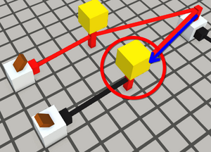
- In Logic World, Backpropagation is an undesired propagation of a signal from an output back into an input. It can be the cause of obscure logic bugs that are often difficult to diagnose.
A solution to this by using fast gates will be discussed later. Here I will show a hacky way: connecting multiple wires together from output pins. You may notice that in the screenshot on the right, the output pin from the button is connected to a lamp and then the lamp is connected to another gate. In general, if a wire is connected between normal pins, it will allow the signal to travel everywhere. The exception is the output pin. Wires coming out of output pins do not conduct signals backward. To use it, you need to connect all the affected items to all the related output pins individually. You can always find the output pin by its big fat size. The next screenshot below shows the correct way.
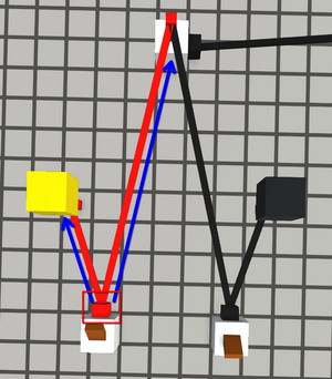
If you do it correctly, you won't need additional gates to stop backpropagation. The drawback is that it requires a direct path from all the inputs to the outputs.
Also, in complex circuits it becomes hard to see individual wires.
Moving on to other techniques to remove unnecessary gates. This part will require some logic understanding. In many cases, you can improve the circuit by just using a different formula than the one you initially thought of. And remember the lack of OR gates, some circuit variations are simply simpler. For example, you need , this will require 2 explicit AND gates. But you can rewrite it as . Notice in the screenshot that a different formulation leads to a smaller circuit.
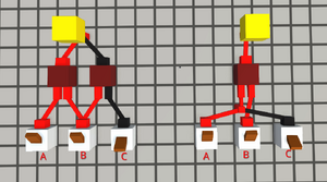
Although this simple example doesn't improve speed (because it's not sequential), this lesson still shows that you can remove unnecessary gates.
The most useful thing to know here is De Morgan's laws. They allow you to rewrite common formulas from one form to another. There could be other examples, but just remember, this part will become easier with experience and overall logic understanding.
A bit more complex technique is to use negations. This often requires a complete rethinking of the design. But when done correctly, it can lead to a significant reduction in the number of gates, especially in very big circuits. You need to stop thinking in terms of ON/OFF to enable/disable something. For example, you can use OFF to indicate the enabled state in some part. This will already remove a NOT gate from the design.
Use fast gates
In Logic World there are so-called fast gates, such as relays or fast buffers. These gates don't have a delay to propagate the signal. This is far from real life, but if you learn to use them correctly, they can significantly speed up your circuits. Let's break them down.
- Fast Buffer is a simple gate that just propagates the signal from input to output without any delay. The main purpose is to avoid backpropagation. It's also useful to route wires neatly.
- The drawback is that it's very bulky, increasing the circuit size significantly.
- Relay is a gate that also propagates the signal without delay, but only if enabled. It's different from Fast Buffers in two major ways:
- It propagates signals both ways, so it can't be used to avoid backpropagation.
- Enabling it takes 1 tick, but after it's enabled, it will propagate the signal without delay.
While fast gates increase the overall number of gates, they remove delays. So you can use Fast Buffer to replace regular buffers and Relays to replace AND gates. But remember, sometimes you still need regular Buffers to synchronize signals. Otherwise, signals coming from fast gates may not match with signals from other gates. Please note, that extensive usage of fast gates may lead to slower performance, as all connected gates updated all at once each tick.
A notable example of a circuit with fast gates is an Instant Carry Adder (ICA).
Mods
There are many mods that add complex circuits as single black boxes, and they usually take 1 tick to perform the function. Examples: CPUs, RAMs, Displays, Keyboards, Network devices, Decoders, Buffers, etc.
Performance
Even if you design a very fast circuit, it may be too big for the game to handle, especially on high tickrates, leading to lags or slower execution overall. You may want to trade off some circuit speed for better simulation performance. Usually it may be done by splitting the circuit into smaller parts that are activated only when needed. The heaviest parts are usually decoders (by themselves or with RAM), HDDs, LUTs. Let's say you have a huge decoder with 1024 outputs. In a naive design, it will activate all the gates at once, leading to a big lag spike. How do you optimize it? You can do it by iteratively converging on the output, using the divide and conquer approach. For example, split the computation into two iterations:
- First iteration: a 3-bit decoder, effectively multiplexing the input between 8x parts.
- Second iteration: only one active 7-bit decoder among 8 parts, with 128 outputs.
You can divide it however you want, the main idea is to reduce the number of gates activated at once.
Next advice is especially important on servers with multiple people. Make sure all your circuits can halt. Even if it's small timer - add a switch. If you are not using a circuit, turn it off.
Size
If you focus only on speed or performance, you may end up with a huge circuit that is hard to build and manage. Sometimes you need to optimize purely for size. Minimizing the size will make you avoid bulky fast gates, introduce cycles, remove parallelism, etc., often leading to slower circuits. But for some designs it may still be worth it. We will not be focusing on designing a logic with a smaller footprint. Instead, here are structural tips that some people find useful:
- Use "round" or "hollow" designs.
- Use 1-tile stackable parts.
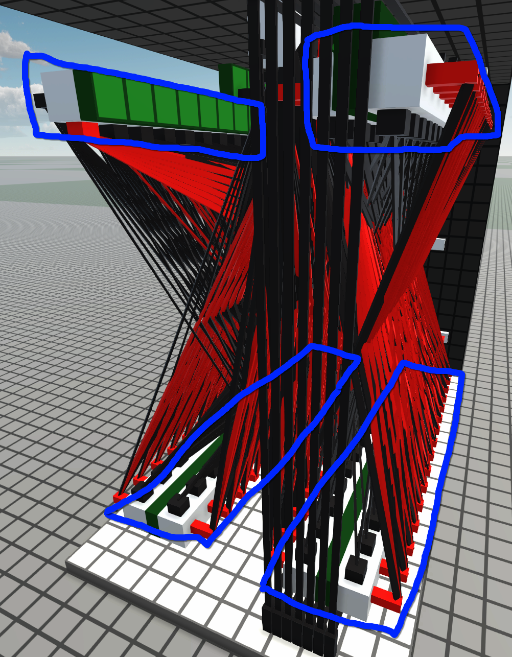
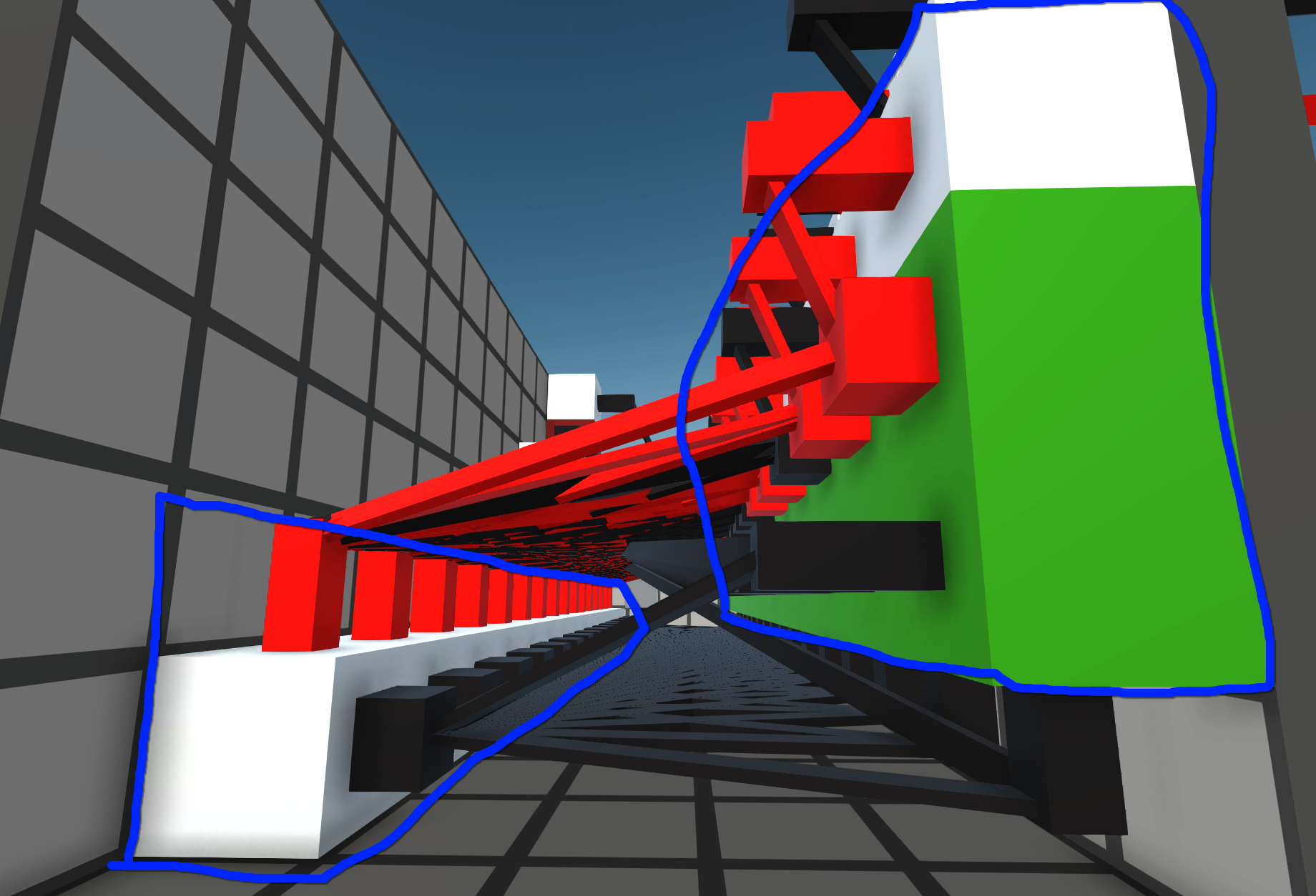
These "round" or "hollow" designs are made by placing supporting structures at the edges or against each other and putting logic and wiring in the middle of it. Always remember, Logic world is 3D! This approach is extremely useful for wiring, as it allows you connect everything to everything. Examples:
