XOR Gate: Difference between revisions
Appearance
m Fix casing |
Lawrziepan (talk | contribs) m Changed timing scenario to correct definition of only one input is on |
||
| Line 17: | Line 17: | ||
== Timing == | == Timing == | ||
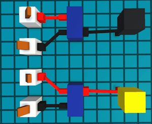
[[File:XOR gate activation delay.png|thumb|A demonstration of two XOR gates being activated. The top XOR gate has one of its inputs active, but its output is not yet active because a delay of 1 tick has not yet passed. The bottom XOR gate has had one of its inputs active for at least 1 tick, and its output is therefore active.]] | [[File:XOR gate activation delay.png|thumb|A demonstration of two XOR gates being activated. The top XOR gate has one of its inputs active, but its output is not yet active because a delay of 1 tick has not yet passed. The bottom XOR gate has had one of its inputs active for at least 1 tick, and its output is therefore active.]] | ||
The XOR gate has a latency of 1 tick, so in the instance when | The XOR gate has a latency of 1 tick, so in the instance when one input is {{on}}, the output will become active 1 tick later. As demonstrated in the example on the right. | ||
== Configurability == | == Configurability == | ||
Revision as of 22:08, 7 September 2025
 XOR gate | |
| Component info | |
|---|---|
| Internal ID |
MHG.XorGate |
| Configurable | No |
| Input and output | |
| Input count | 2 |
| Output count | 1 |
| Propagation delay | 1 tick |
The XOR gate is a basic digital logic component whose output will be ON if only one of its inputs are ON.
An XOR gate is 2 tiles wide and 1 tile tall, and its body is 1 tile long, but its inputs and outputs extend its area to 3 tiles.
Logic
The XOR gate's output will only be active if one of its inputs are ON.
| Input 1 | Input 2 | Output |
|---|---|---|
| 0 | 0 | 0 |
| 1 | 0 | 1 |
| 0 | 1 | 1 |
| 1 | 1 | 0 |
Below are alternative XOR definitions.
The XOR gate's output will only be ON:
- if inputs are not equal.
- Helpful to compare values.
- if number of ON inputs is odd.
- Helpful for XOR's with multiple inputs.
Timing

The XOR gate has a latency of 1 tick, so in the instance when one input is ON, the output will become active 1 tick later. As demonstrated in the example on the right.
Configurability
The XOR gate cannot have its number of inputs changed, but can have its output position flipped by pressing 'F' on it. The bottom XOR gate in the image on the right has had its output flipped.

