Lookup Table: Difference between revisions
Made it much simpler by removing some wording. Added a LUT definition using a template. Made formulas clearer. |
m Make external link external |
||
| Line 1: | Line 1: | ||
Any arbitrary logic formula can always be represented in [ | Any arbitrary logic formula can always be represented in [https://en.wikipedia.org/wiki/Disjunctive_normal_form disjunctive normal form]. Put in simple terms, the output of the formula is computed using a single OR operation on its inputs coming from a number of AND gates. Each AND gate represents a distinct case where the output is supposed to be ''true''. | ||
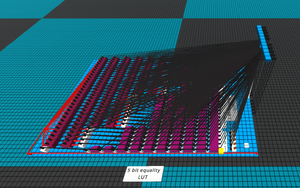
[[File:5BitEqualityLut.png|alt=5 bit equality LUT|thumb|5 bit equality LUT]] | [[File:5BitEqualityLut.png|alt=5 bit equality LUT|thumb|5 bit equality LUT]] | ||
Revision as of 20:47, 7 September 2025
Any arbitrary logic formula can always be represented in disjunctive normal form. Put in simple terms, the output of the formula is computed using a single OR operation on its inputs coming from a number of AND gates. Each AND gate represents a distinct case where the output is supposed to be true.

- Lookup table
- In Logic World, a Lookup table (LUT) is a circuit that explicitly encodes all possible input cases and assigns a specific output to each case.
- The output may be a single bit or a pattern of bits.
- Examples:
- read-only memory (ROM) (general example)
- storing characters for a screen (particular example)
- a hard-coded complex formula.
Construction
A LUT is implemented by first creating a list of all input combinations that should lead to a true output. From this list, the LUT can then be built quite easily. It consists of multiple relay chains that are simply OR-ed together at the end, where one chain corresponds to one input-assignment that should lead to a truthy output value. The aforementioned relay chains are started by a single NOT-gate whose inputs are all signals that are false in the case where a true output is expected, followed by a set of relays where the top input is expected to be true for such a true result.
We can avoid delays by not using buffers, it will make circuit perform the operation in a single tick! In that case, back-propagation must be prevented by using fast-buffers. In this case each chain needs one component per input (relays plus fast-buffers), along with one NOT-gate if there are any inputs that are supposed to be off.
Complexity to build
When building a LUT as described above, we can count the total number of components as:
Where:
is the number of distinct chains (true outputs),
is the number of inputs.
Let's assume half of all possible input combinations lead to a true output:
So in total:
In theory it's asymptotically approaching :
In other words, the required component count grows exponentially with the number of inputs, assuming the number of true-output cases also scales exponentially.
While LUT circuits become very expensive in terms of components, they are the extremely fast, producing an output in a single tick regardless of input size. This makes them essential for designs that must run within strict time limits. For non-trivial functions, this speed is usually only achievable by using a LUT.

