| Input 1 | Input 2 | Output |
|---|---|---|
| 0 | 0 | 0 |
| 0 | 1 | 0 |
| 1 | 0 | 0 |
| 1 | 1 | 1 |
AND Gate: Difference between revisions
use auto truth table |
m use algebraic formula |
||
| Line 23: | Line 23: | ||
| outputs=1 | | outputs=1 | ||
| caption=AND Gate Truth Table (2 inputs) | | caption=AND Gate Truth Table (2 inputs) | ||
| expr1=a b | | expr1=a & b | ||
}} | }} | ||
|-|3 Inputs= | |-|3 Inputs= | ||
| Line 30: | Line 30: | ||
| outputs=1 | | outputs=1 | ||
| caption=AND Gate Truth Table (3 inputs) | | caption=AND Gate Truth Table (3 inputs) | ||
| expr1=a b c | | expr1=a & b & c | ||
}} | }} | ||
|-|4 Inputs= | |-|4 Inputs= | ||
| Line 37: | Line 37: | ||
| outputs=1 | | outputs=1 | ||
| caption=AND Gate Truth Table (4 inputs) | | caption=AND Gate Truth Table (4 inputs) | ||
| expr1=a b c d | | expr1=a & b & c & d | ||
}} | }} | ||
</tabber> | </tabber> | ||
Revision as of 16:18, 8 September 2025
 AND gate with two inputs | |
| Component info | |
|---|---|
| Internal ID |
MHG.AndGate |
| Configurable | Yes |
| Input and output | |
| Input count | Adjustable from 2 to 4 |
| Output count | 1 |
| Propagation delay | 1 tick |
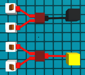
The AND gate is a basic digital logic component whose output will be ON if all its inputs are ON.
For a 2 input AND gate, it is 1 tile wide and 1 tile tall, and its body is 1 tile long, but its inputs and outputs extend its area to 3 tiles.
Logic
The AND gate's output will only be active if all of its inputs are ON. This is true no matter how many inputs the AND gate has.
| Input 1 | Input 2 | Input 3 | Output |
|---|---|---|---|
| 0 | 0 | 0 | 0 |
| 0 | 0 | 1 | 0 |
| 0 | 1 | 0 | 0 |
| 0 | 1 | 1 | 0 |
| 1 | 0 | 0 | 0 |
| 1 | 0 | 1 | 0 |
| 1 | 1 | 0 | 0 |
| 1 | 1 | 1 | 1 |
| Input 1 | Input 2 | Input 3 | Input 4 | Output |
|---|---|---|---|---|
| 0 | 0 | 0 | 0 | 0 |
| 0 | 0 | 0 | 1 | 0 |
| 0 | 0 | 1 | 0 | 0 |
| 0 | 0 | 1 | 1 | 0 |
| 0 | 1 | 0 | 0 | 0 |
| 0 | 1 | 0 | 1 | 0 |
| 0 | 1 | 1 | 0 | 0 |
| 0 | 1 | 1 | 1 | 0 |
| 1 | 0 | 0 | 0 | 0 |
| 1 | 0 | 0 | 1 | 0 |
| 1 | 0 | 1 | 0 | 0 |
| 1 | 0 | 1 | 1 | 0 |
| 1 | 1 | 0 | 0 | 0 |
| 1 | 1 | 0 | 1 | 0 |
| 1 | 1 | 1 | 0 | 0 |
| 1 | 1 | 1 | 1 | 1 |
Timing

The AND gate has a latency of 1 tick, so in the instance when all inputs are ON, the output will become active 1 tick later. As demonstrated in the example on the right.
Configurability
Pressing the edit button on an AND gate allows you to change the number of inputs it has. You can select 2, 3, or 4 inputs.
Changing the number of inputs on an AND gate does not change its latency, but it does make the components bigger, with their width changing from 1 tile wide with 2 inputs to a little less than 2 tiles wide with 3 inputs, to 2 tiles wide with 4 inputs.
Note that when an AND gate has 3 inputs, while its width is less than 2 tiles, the component is centered on a tile, causing it to require 3 tiles of width.
Smaller components such as pegs and other 3 input AND gates can still occupy the adjacent tile. But other components that take up a full tile will need to be moved over.

