D Latch: Difference between revisions
mNo edit summary |
Add missing navbox |
||
| Line 32: | Line 32: | ||
D Latches have two attachment points, one for each square covered by the body of the component. These attachment points can be placed in the center of a [[Circuit Board]] square or on top of a [[Mount]]. | D Latches have two attachment points, one for each square covered by the body of the component. These attachment points can be placed in the center of a [[Circuit Board]] square or on top of a [[Mount]]. | ||
{{Navbox components}} | |||
[[Category:Vanilla components]] | [[Category:Vanilla components]] | ||
[[Category:Circuitry components]] | [[Category:Circuitry components]] | ||
Revision as of 00:53, 9 September 2025
 D Latch | |
| Component info | |
|---|---|
| Internal ID |
MHG.DLatch |
| Configurable | No |
| Input and output | |
| Input count | 2 |
| Output count | 1 |
| Propagation delay | 1 tick |
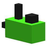
The D Latch is a component used for digital logic. The state of its output can be "latched", or set, to a certain state. This is useful for saving data and reading it back later.
Behavior
The D Latch has an input on the side ("data"), an input on the top ("enable"), and an output on the top. The input on the side is a state to be latched; when the enable input is Template:ON, the output state will be latched to the enable input's state.
This behavior is represented by the following truth table, where * represents the previous state:
| Data | Enable | Output |
|---|---|---|
| 0 | 0 | * |
| 0 | 1 | 0 |
| 1 | 0 | * |
| 1 | 1 | 1 |
The D Latch takes one tick to update the state of its output after a change to the state of its inputs.
Placement
D Latches have two attachment points, one for each square covered by the body of the component. These attachment points can be placed in the center of a Circuit Board square or on top of a Mount.

