Edge Detection: Difference between revisions
N00basaurus (talk | contribs) Added Edge Detection page |
improved formatting and did todo |
||
| Line 1: | Line 1: | ||
Edge detection is the | '''Edge detection''' is the process of sending a signal at the moment a signal transitions. | ||
A '''rising edge''' refers to the instant when a signal changes from ''off'' to ''on''. | |||
A '''falling edge''' refers to the instant when a signal changes from ''on'' to ''off''. | |||
== Circuit Implementation == | == Circuit Implementation == | ||
[[File:Raising-edge-detector.png|thumb|right|alt=Raising edge detector|Raising edge detector]] | |||
You can detect a rising edge by | You can detect a rising edge by checking whether the input signal was ''off'' some number of [[Tick|ticks]] ago but is now ''on''. | ||
This can be done using an [[AND Gate]] and an [[Inverter]]. | |||
Connect one input of the AND gate directly to your signal, and connect the other input through the inverter. | |||
When the input signal turns on, the direct input to the AND gate is immediately on. The inverter output, however, is delayed by 1 tick, so it remains ''on'' for one more tick. | |||
Since both inputs of the AND gate are ''on'', it becomes marked for activation in the next tick. | |||
On the next tick, the AND gate turns ''on'' while the inverter output turns ''off''. At this point, not all AND gate inputs are ''on'', so it will be marked to turn ''off'' on the following tick. | |||
The pulse length is determined by the delay between the direct and inverted inputs of the AND gate. | |||
You can extend the pulse to 2 ticks using a [[Buffer]], or make it 2 ticks or longer with a [[Delayer]]. | |||
== Example Signal Diagram == | |||
Below is an example timing diagram showing how a rising edge detector behaves: | |||
* '''Input''' shows the original signal toggling between off and on. | |||
* '''Output''' is the short pulse generated on each rising edge of the input signal. | |||
{{Binary signal | |||
| signals=Input, Output | |||
| signal1=000011110000111 | |||
| signal2=000010000000100 | |||
}} | |||
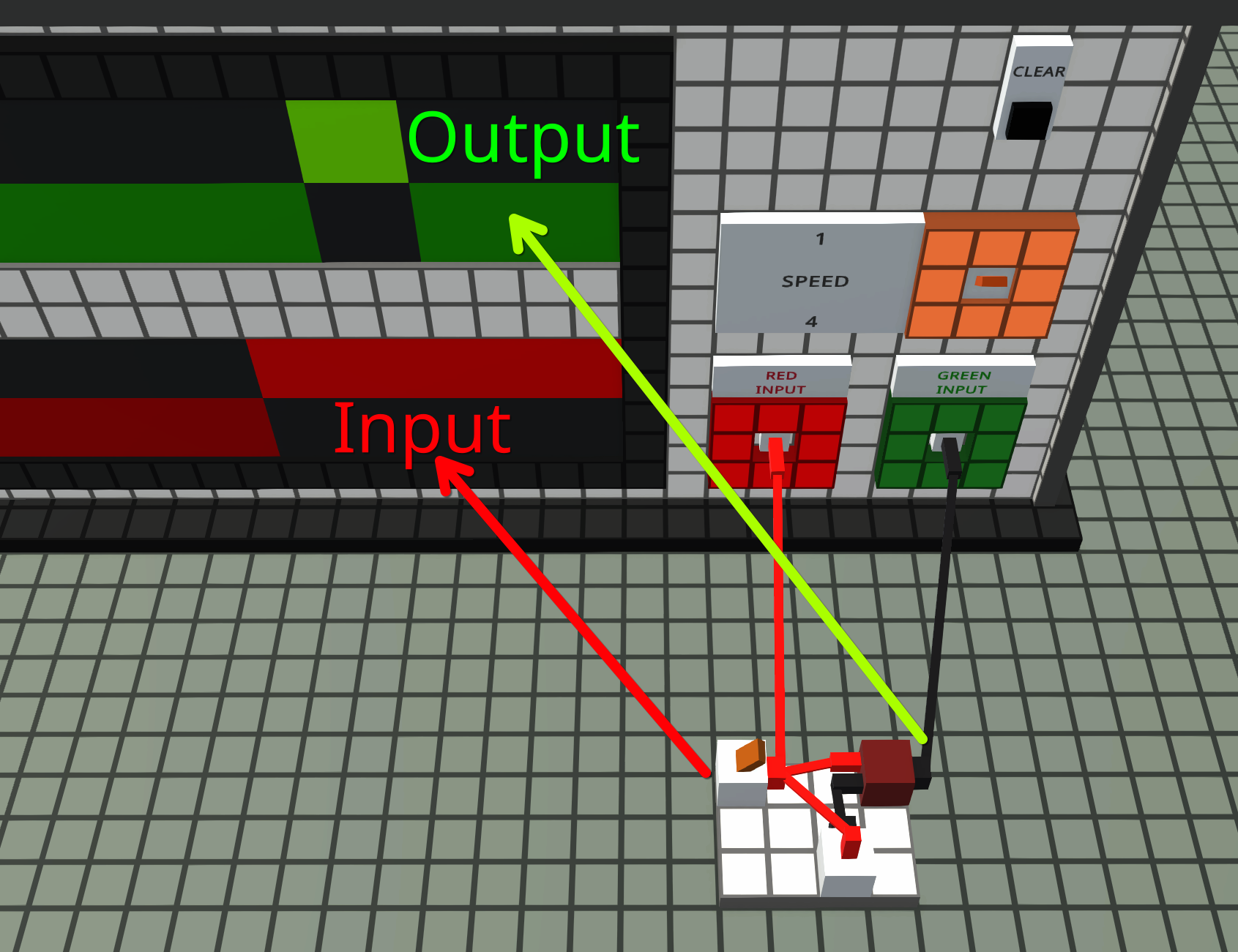
How it looks in the Logic World: | |||
[[File:edge-oscillator.png|frame|center|alt=oscilloscope|Raising Edge on oscilloscope ]] | |||
Revision as of 18:02, 7 October 2025
Edge detection is the process of sending a signal at the moment a signal transitions.
A rising edge refers to the instant when a signal changes from off to on.
A falling edge refers to the instant when a signal changes from on to off.
Circuit Implementation

You can detect a rising edge by checking whether the input signal was off some number of ticks ago but is now on.
This can be done using an AND Gate and an Inverter. Connect one input of the AND gate directly to your signal, and connect the other input through the inverter.
When the input signal turns on, the direct input to the AND gate is immediately on. The inverter output, however, is delayed by 1 tick, so it remains on for one more tick. Since both inputs of the AND gate are on, it becomes marked for activation in the next tick.
On the next tick, the AND gate turns on while the inverter output turns off. At this point, not all AND gate inputs are on, so it will be marked to turn off on the following tick.
The pulse length is determined by the delay between the direct and inverted inputs of the AND gate. You can extend the pulse to 2 ticks using a Buffer, or make it 2 ticks or longer with a Delayer.
Example Signal Diagram
Below is an example timing diagram showing how a rising edge detector behaves:
- Input shows the original signal toggling between off and on.
- Output is the short pulse generated on each rising edge of the input signal.
| 0 | 1 | 2 | 3 | 4 | 5 | 6 | 7 | 8 | 9 | 10 | 11 | 12 | 13 | 14 | 15 | ||
| Input | |||||||||||||||||
| Output | |||||||||||||||||
How it looks in the Logic World:


