
File:A schematic view of a very basic control unit.png
Original file (670 × 724 pixels, file size: 35 KB, MIME type: image/png)
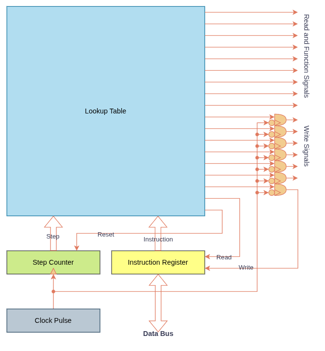
A lookup table takes in as its inputs the content of a step counter and an instruction register, and produces as its outputs various read, write, and function signals. On the clocks rising edge, the step counter is incremented. The lookup table immediately updates its outputs, reading from various components and sending function signals. The write signals do not get sent out though until the falling edge of the clock.
As this diagram suggests, the lookup table is in control of its own instruction register, and has the ability to reset the step counter. The instruction register is updated at the beginning of every instruction sequence, and the step counter is reset at the end of every instruction sequence.
File history
Click on a date/time to view the file as it appeared at that time.
| Date/Time | Thumbnail | Dimensions | User | Comment | |
|---|---|---|---|---|---|
| current | 15:00, 12 October 2025 | | 670 × 724 (35 KB) | N00basaurus (talk | contribs) |
You cannot overwrite this file.
File usage
The following page uses this file: