Clock
A Clock is a circuit that changes its output state periodically over time.
The simplest clock is made of a single Inverter connected to itself, either directly or with a delay. A single inverter clock alternates ON and OFF every tick. With delayer components, it will have a longer period.
Terminology
- Period is the duration of the entire cycle of the clock, measured in ticks. It includes the duration of the ON output and the OFF output.
- Duration of a signal is the number of ticks the signal remains unchanged.
- Frequency is the rate at which the clock repeats its cycle. It shows how many full cycles (periods) occur per unit of time.
Measuring frequency
In Logic World, the simulation runs at a adjustable Tick Rate (number of ticks per second). Since period is measured in ticks, the real-time frequency can be calculated as:
For example, with a tick rate of 60 and a clock period of 12 ticks:
Increasing the tick rate or reducing the clock period increases frequency.
Measuring delays
With delay components, the duration of a signal is calculated as follows:
The full period will be:
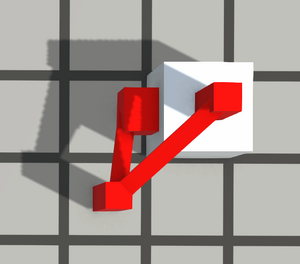 |
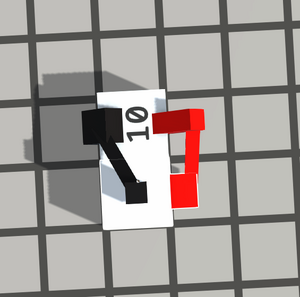 |
In advanced circuits or during construction you may require clocks with different periods, signal shapes, and functionality. Good clocks are essential in complex designs.
Clock signal diagrams
Below are examples of different clock signals patterns for better understanding:
| 0 | 1 | 2 | 3 | 4 | 5 | 6 | 7 | 8 | 9 | 10 | 11 | 12 | 13 | 14 | 15 | 16 | 17 | 18 | ||
| Alternating | ||||||||||||||||||||
| Square | ||||||||||||||||||||
| Pulsating | ||||||||||||||||||||
| Complex | ||||||||||||||||||||
Construction
This article is mostly agnostic towards the period of the clock. This means you may add different features that will work regardless of the period.
To make a good clock you need to know what functionality you require. Here is a list of possible features you may want:
- Turning on/off
- Manually adjustable period
- Digitally adjustable period
- Specific signal shape
This article will show how to add features to a clock, starting from the simplest to the most advanced.
Turning on/off
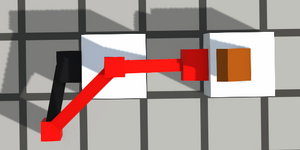
Any clock has an inverter, therefore it can always be turned off by applying an ON signal to it. It is good practice to add a switch to every clock. If you want to use buttons to turn the clock on/off, you can add a T Flip-Flop, a Set-Reset Flip-Flop, or similar components.
Adjustable period
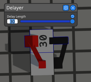
You can adjust the period either manually or digitally. If you are using a delayer, you can edit its delay up to 30 ticks. Remember that with the inverter, the total duration will be 1 tick longer. For periods longer than 30 ticks, connect several delayers in series.
Another approach is to build multiple clocks with different periods and enable one of them. This method also allows digital or programmatic period control by selecting the clock with the required period, usually with a multiplexer.
Signal shape
Simple clock will have a "square wave" signal, where output is alternating between ON and OFF with an equal duration. Quite often you will need a clock with a long period but producing a 1 tick pulse each cycle.
It is possible to achieve this by building a loop with multiple buffers and passing a 1-tick signal through it, but it will quickly become impractical.
A more efficient way is to attach a separate pulse generator to a normal clock. It will work with any clock configuration.
For long periods and long pulses, you can use the following design: clock → pulse generator → signal extender.
"Multitool" clock example
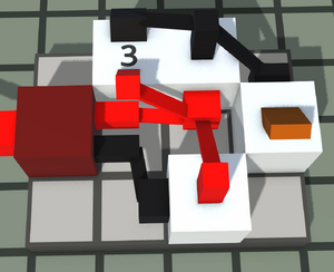
It is a good idea to construct a small but efficient clock for general use. The example on the right screenshot combines all key features: a power switch, adjustable period, and pulse output. It's a good idea to have it saved as a subassembly. The total period here is 8 ticks, and you can see the signal shape on the next screenshot below.


